VERIFIED PROJECT EXPERIENCE

Industrial Building Project Experience

Real Shri Satiji project evidence, technical records and execution-stage proof from the company's own archive.

Named source-backed projects are presented where the archive supports the identity, location and project context. Anonymised technical visuals remain useful where the engineering lesson matters more than the client identity.

Publication rule: Project names, locations, technical facts and project evidence may be published from Shri Satiji records. Quotation prices, rates, commercial amounts and security-sensitive personal data remain excluded.

ILLUSTRATIVE SITE ARRANGEMENTGeneric industrial building arrangement illustrationFour invented industrial building forms in an abstract site arrangement, without project measurements or client geometry.ARRANGEMENT REVIEWILLUSTRATIVE GEOMETRY • NO PROJECT SCALE
Fresh generic schematic illustration, rebuilt for this page. It does not depict a client site or completed project.
NO PROJECT MEASUREMENTS

PROJECT EXPERIENCE

Project Experience That Supports Practical Building Decisions

Industrial building requirements vary by application, span, storage, equipment, movement, envelope and future expansion. Our project experience is presented around the practical decisions that influence engineering, planning and execution across Maharashtra.

This page now combines named project evidence from Shri Satiji's own records with anonymised technical reference visuals. Exact dimensions or structural details are published only when the source record supports them; quotation prices, rates and commercial amounts are not published.

NAMED PROJECT EVIDENCE

Source-backed projects from the Shri Satiji archive.

These examples use company-owned records to show real project identity, location, technical context and execution stages. Unsupported details are not added.

NAGPUR

Sahyadri Farm

Industrial / Farm ShedLean-ToErection + Sheeting

Shri Satiji records document the Nagpur project at two distinct stages: lean-to shed erection and main-site sheeting.

SAMBHAJINAGAR

Rushikesh Logistics

Logistics / WarehouseShed 1 + Shed 2Erection + Sheeting

Shed 1 is documented through erection and sheeting stages, while Shed 2 is separately documented during erection.

MALKAPUR

Eco Biotech

Industrial ShedStructural FrameCompleted Interior Evidence

The project record follows Eco Biotech from structural-frame erection through sheeting and the completed shed interior.

PROOF PATTERN 01

Drawing-Controlled 3D Coordination

For a multi-building industrial development, review can connect building arrangement, open or closed wall intent, openings, canopies and relationships between building forms to controlled drawings.

Only supported geometry and dimensioned features are represented. The visual helps frame review and discussion; technical items outside the agreed basis remain subject to approved engineering documents.

Generic industrial building arrangement illustrationFour invented industrial building forms in an abstract site arrangement, without project measurements or client geometry.ARRANGEMENT REVIEWILLUSTRATIVE GEOMETRY • NO PROJECT SCALE
Illustrative arrangement diagram only; no source drawing, project geometry, scale or client details are shown.

PROOF PATTERN 02

Structural Verification Workflow

For a crane-capable multi-span industrial building, the engineering workflow reconciles available inputs, reviews strength and serviceability, and considers second-order effects and reciprocal bracing where applicable to the agreed basis.

Member selection and quantities follow the engineering scope. Unresolved vendor or engineering inputs remain visible as hold points until the responsible information is confirmed.

GENERIC FRAME + REVIEW PATHGeneric multi-span structural frame illustrationAbstract steel frame with multiple bays and a schematic verification path, without engineering values.INPUTSANALYSISCHECKREVIEW
InputsAnalysisStrength / Serviceability CheckEngineering ReviewHold PointsApproved Documents
Generic engineering workflow, not a calculation result. No project values, sizes or member schedules are presented.

PROOF PATTERN 03

Facade / Colour / 3D Visual Decision Support

Fresh concept alternatives can help teams discuss facade character, colour direction, openings and the overall building view before downstream information is finalised.

These visual choices support discussion. Final construction follows approved engineering and project documents and the agreed project scope.

GENERIC FACADE PALETTE CONCEPTS
Concept palette ANeutral envelope with warm accent
Concept palette BCool-toned wall and roof study
Concept palette CMuted finish with clear entry band
Generic coded facade studies, made for decision support. They are not photographs or client-specific geometry.

PROOF PATTERN 04

Requirement-to-Execution Documentation Discipline

Project work moves through requirement capture, drawing review, scope clarification, proposal development, revisions, approval and downstream execution coordination.

Revision control, scope boundaries, exclusions and hold points help keep responsibilities clear as information moves between project stages.

GENERIC DOCUMENTATION SEQUENCE
  1. Requirement capture
  2. Drawing review
  3. Scope clarification
  4. Proposal & basis
  5. Revision control
  6. Approval / hold points
  7. Execution coordination
Illustrative sequence only. Actual deliverables and hand-offs depend on the agreed project scope.

TECHNICAL PROJECT PROOF

Drawing-Based Evidence for Practical Building Decisions

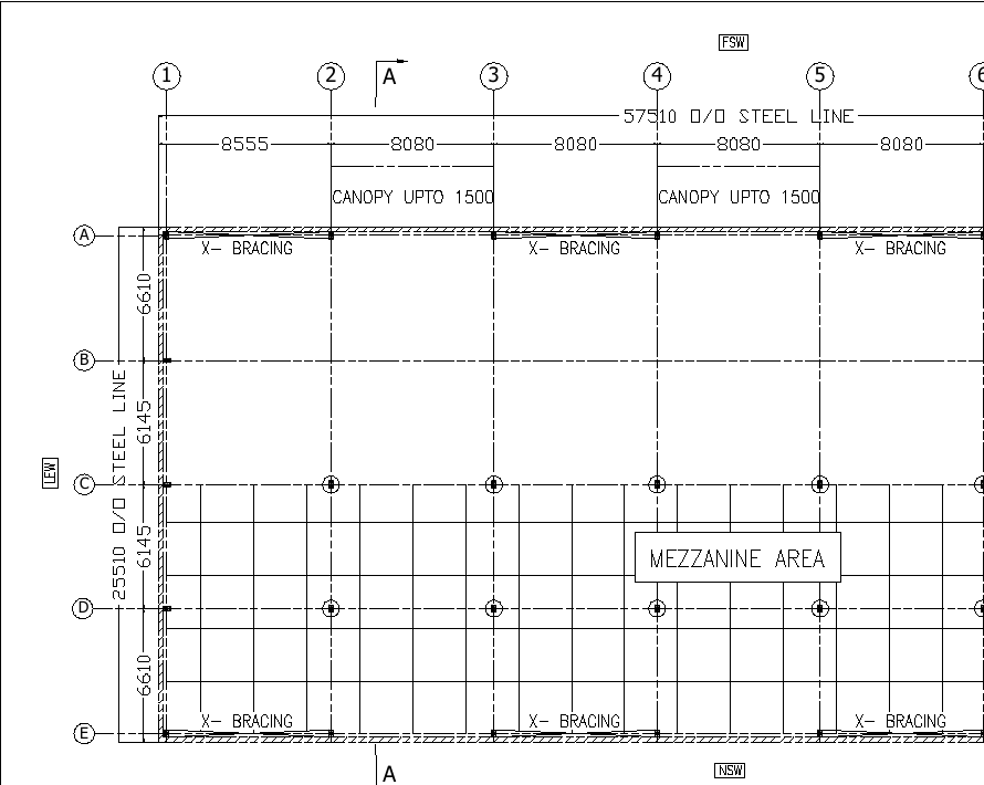
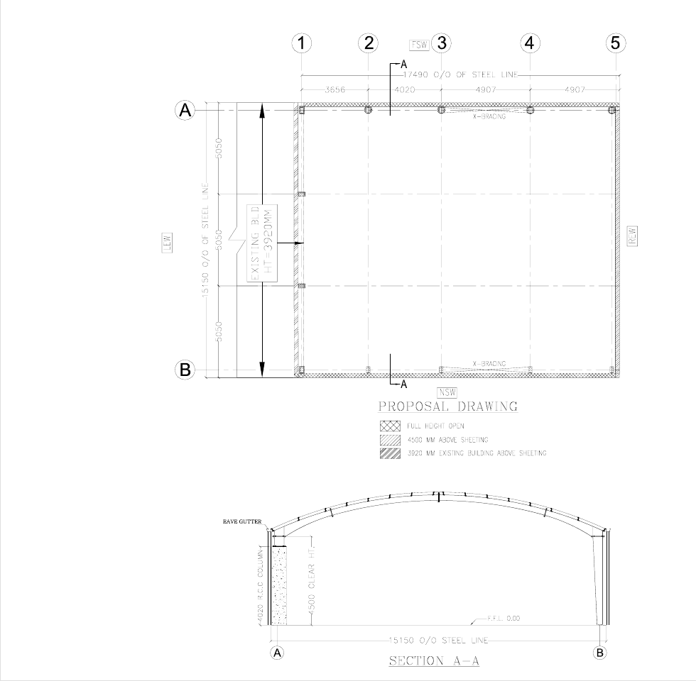
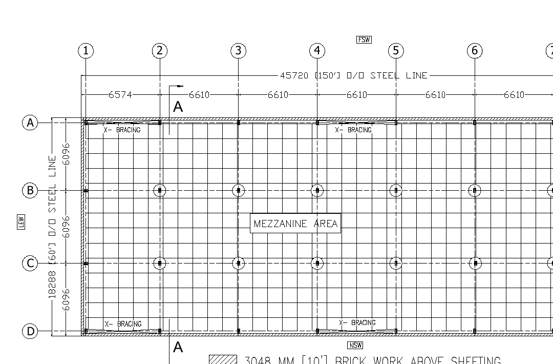
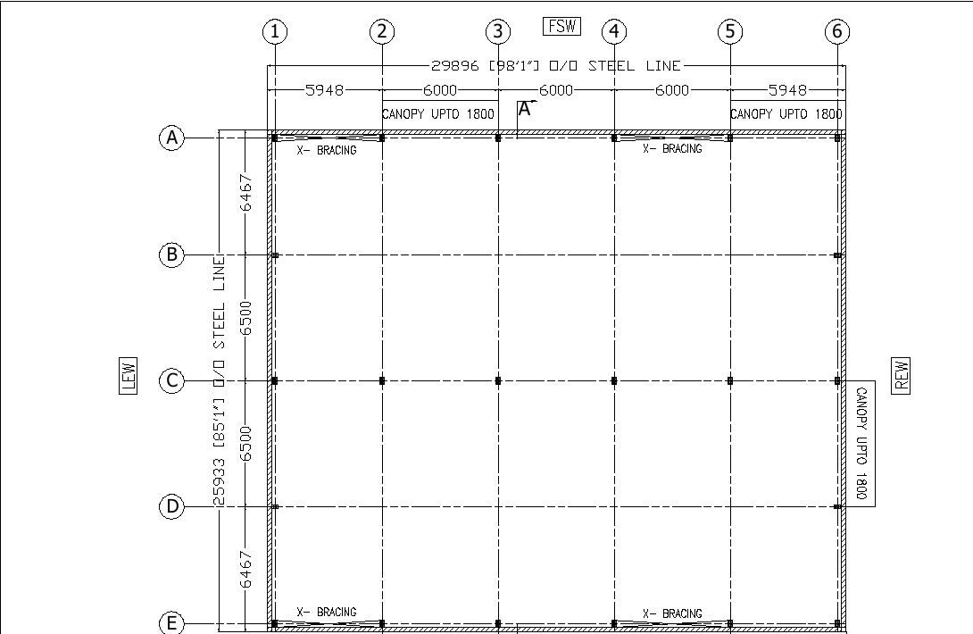
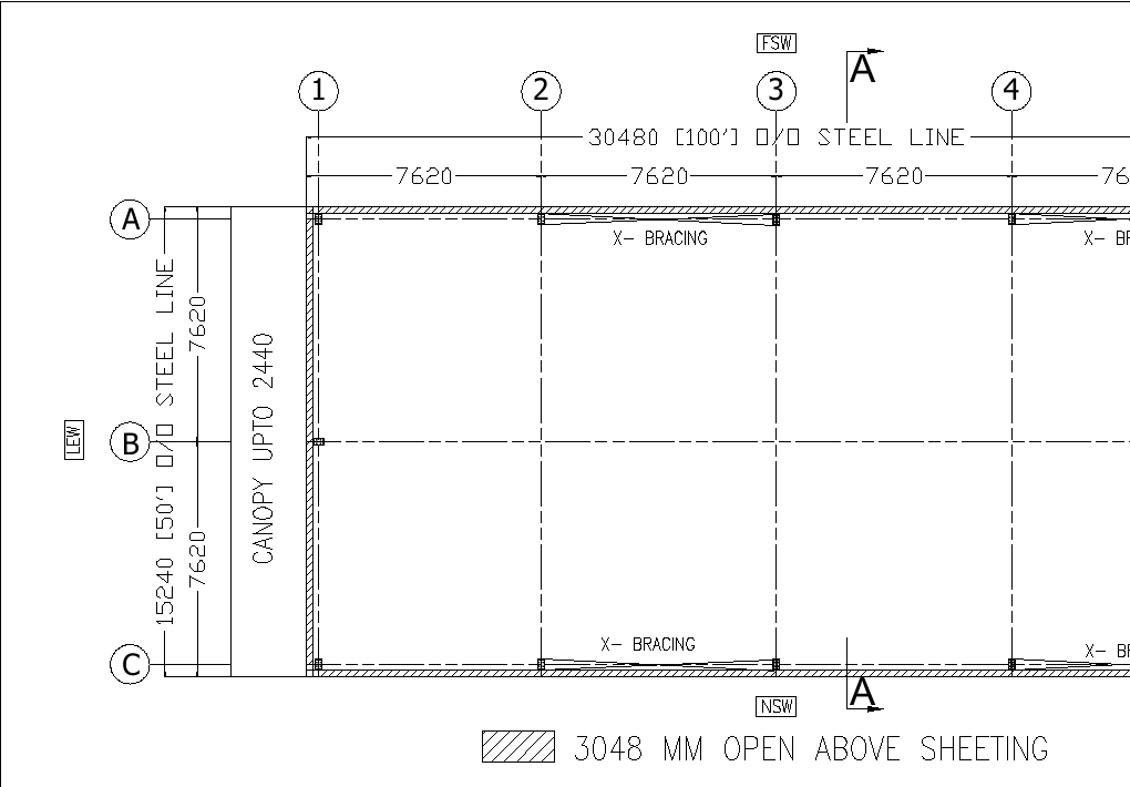
Selected anonymised technical visuals show the kind of plan, section and framing information that supports industrial-building coordination, mezzanine planning, bracing review and envelope decisions.

These reference visuals are derived from project documentation with title-block and commercial details removed. They do not identify a client or site and do not represent completion, approval or a construction result.

Anonymised steel-frame plan showing mezzanine and canopy coordination
Steel-frame plan with mezzanine, canopy and bracing coordination.
Anonymised industrial-building plan and section reference
Plan and section reference for clear-height and envelope discussion.
Anonymised multi-bay steel-frame mezzanine plan
Multi-bay steel-frame plan showing mezzanine and bracing intent.
Anonymised warehouse steel-frame plan
Warehouse-style plan showing bay spacing, bracing and canopy notation.
Anonymised industrial warehouse framing plan
Industrial framing plan showing grid, canopy and open-above-sheeting notation.

The visuals are provided for technical context only. Final engineering, fabrication and construction follow the approved project basis and agreed scope.

PLAN THE NEXT TECHNICAL STEP

Share your requirement. We’ll structure the next technical step.

Start with the application, site context, building use, operating needs and available controlled information.

WhatsApp